Most of the seal failures we investigate trace back to the drawing rather than the moulding. Every field-return analysis we have done points the same way. A well-moulded seal in a badly designed groove leaks; a well-designed groove will put up with a mediocre seal for years. The drawing does more of the work than the material does.
Here are the five drawing decisions that come up again and again on incoming enquiries. If you are designing a housing for an elastomer seal, running through this list at drawing-review stage will save a lot of grief later.
1. Wrong groove volume
The single most common problem. A groove that is too shallow will not accommodate the seal's volumetric swell in service; the seal is over-compressed, extrudes through the gap, and either fails immediately or fails a few thermal cycles in. A groove that is too deep gives the seal insufficient squeeze, and it leaks from day one.
The published guidance for O-ring grooves is well-established. Static face seals want 25–30% cross-section compression. Static radial seals want a similar figure. Dynamic reciprocating seals want less - typically 10–15% - to keep friction and wear manageable. Rotary dynamic applications want less still.
The right number depends on the compound and the fluid. Compounds that swell in the service fluid need less initial squeeze because the fluid will provide additional interference in service. Compounds that shrink in service - silicone in certain solvents - need more.
If the drawing does not specify a target squeeze, we work it out from the seal cross-section, the compound's fluid-swell data and the service environment. When the number falls outside the published windows, we flag it before quoting.
2. Sharp corners in the groove
An elastomer under compression flows into every corner of the cavity it sits in. A sharp internal corner in the groove - a 90° step with no radius - concentrates stress at that corner. Under thermal cycling, that stress becomes a crack initiation site, and the seal fails from the corner outward.
A generous fillet at the base of the groove - typically 0.2 to 0.5 mm depending on cross-section - costs almost nothing to machine and dramatically improves service life. On dynamic seals, the fillet is not optional; on static face seals it is highly recommended.
The corresponding rule for the sealing surface: the leading edges that the seal is installed over must be broken or chamfered. A sharp edge on an installation lead-in will nick the seal on assembly, and a nicked seal leaks.
3. Surface finish specified as "smooth"
"Smooth" is not a specification. It is an aspiration.
The sealing surface roughness determines whether the seal can bed in and form a leak path or not. On a static face seal, Ra 0.4–0.8 μm is the target - smooth enough to seal, rough enough to hold a film of fluid that lubricates seating. On a dynamic shaft seal, Ra 0.2–0.4 μm is typical, with a further specification on surface lay (the direction of machining marks) to prevent the seal being pumped along the shaft.
Both should be specified numerically on the drawing, with the measurement direction called out. "Smooth ground finish" and "polished" are not equivalent to a Ra number.
4. Material specified by trade name only
"Viton" is a family of compounds, not a single compound. Grades vary in cure system (bisphenol, peroxide), fluorine content (65–70% and up), plasticiser content and filler package. Two 70-Shore Vitons from different formulations can have compression set values 15% apart and fluid resistance profiles noticeably different.
The same is true for other trade names: "Buna-N" covers a range of nitrile chemistries; "Silastic" covers a range of silicones; "Kalrez" is a family of FFKM grades that differ by service environment.
If the drawing calls for a specific grade - "Viton A-401C, 70 Shore A" - we can quote and supply to that exact specification. If the drawing calls for "Viton 70 Shore" only, we will ask what the application actually is, and either recommend a specific grade or supply a generic FKM that meets the drawing's letter. The specification block on the drawing is the audit trail; it should say what you actually want.
5. No allowance for thermal expansion
Elastomers expand thermally at rates significantly higher than the metal housings they sit in. A typical rubber has a coefficient of thermal expansion around 200 × 10⁻⁶ /°C, versus steel at around 12 × 10⁻⁶ /°C - roughly seventeen times. Over a 100 °C temperature rise, the seal grows a great deal more than the housing.
A groove sized correctly at ambient can be catastrophically wrong at service temperature. FKM and FFKM in particular are used in high-temperature applications where the thermal delta is large; both need real allowance in the groove volume calculation.
The correct discipline is to size the groove for the seal at service temperature, not at room temperature, and to verify that the room-temperature squeeze is still enough to prevent leakage during start-up.
Bonus: undercuts and installation clearances
Two smaller items that come up regularly.
Undercut grooves - where the top of the groove is narrower than the bottom, to retain the seal during assembly - are a manufacturing feature the drawing needs to specify. They are common on face seals for vertical applications where the seal would fall out at assembly. They also make the seal impossible to remove without destroying it; if the assembly is meant to be serviced, an undercut groove is the wrong choice.
Installation clearances - the diametral clearance between the moving part and the housing on either side of the seal - set the extrusion gap. Above a certain pressure, the seal will extrude into that gap and fail. The gap must be sized for the fluid pressure and the compound hardness, not left to whatever the tolerance stack happens to produce.
What a good drawing looks like
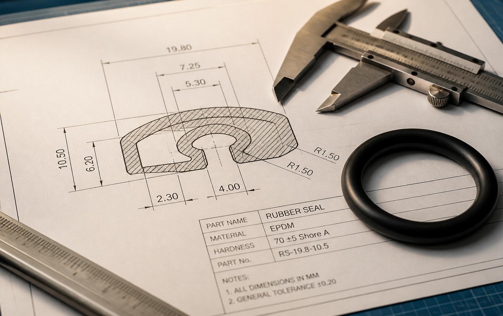
The drawings we quote without follow-up questions have five things in common: groove dimensions with tolerances, surface finish specified numerically, material called out by grade and hardness, fluid and temperature stated in the drawing notes, and any special installation or removal requirements flagged explicitly. Everything else - coating, colour, marking, packing - is preference. Those five are structural.
If you are designing a housing for the first time, or re-drawing a legacy part for re-sourcing, send us an early draft. We would rather comment on a drawing at the design stage than diagnose a leak from a fielded part. Both are things we do; the first is significantly cheaper.